操作Solidworks过程里,很多网友表示自己还不会工程图插入中心符号线,其实操作很简单的,这里笔者就为大伙提供Solidworks工程图插入中心符号线的详细步骤,希望可以帮助到有需要的朋友。
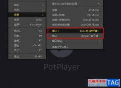
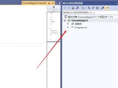
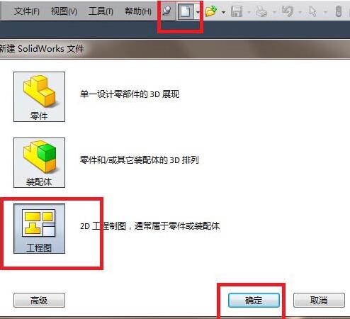
1、如图,打开Solidworks,新建一个工程图文件。具体操作见下图红色框选。
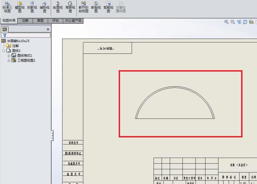
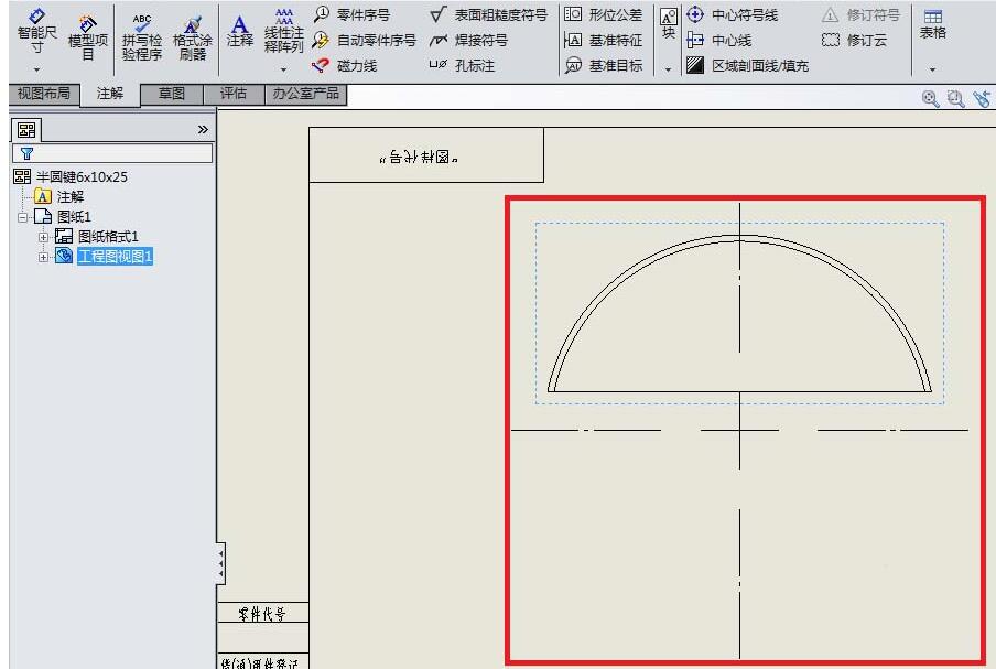
2、如图,新建的这个工程图中的圆弧是没有中心线的,更没有中心符号线,而我们要手动给它添加一个中心符号线。
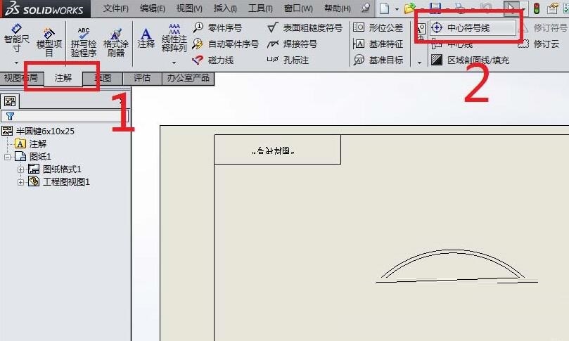
3、如图红色框选、红色数字。
1)点击“注解”,来到注解工具栏
2)找到“中心符号线”图标,点击它。
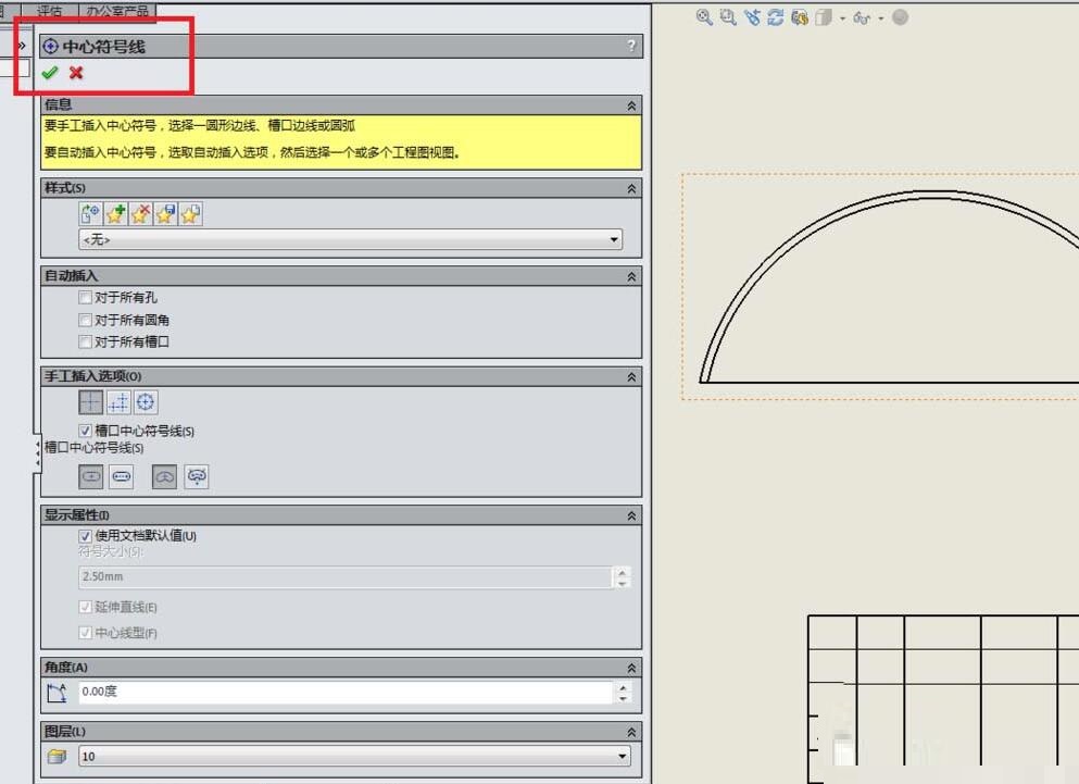
4、如图,弹出了“中心符号线”对话框,若没有特别的要求,那么对话框中的参数设置什么的都可以采用默认。
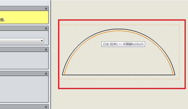
5、选择一个圆弧。如图红色框选所示,那个颜色变成橙色的圆弧段就是笔者选择的圆弧。
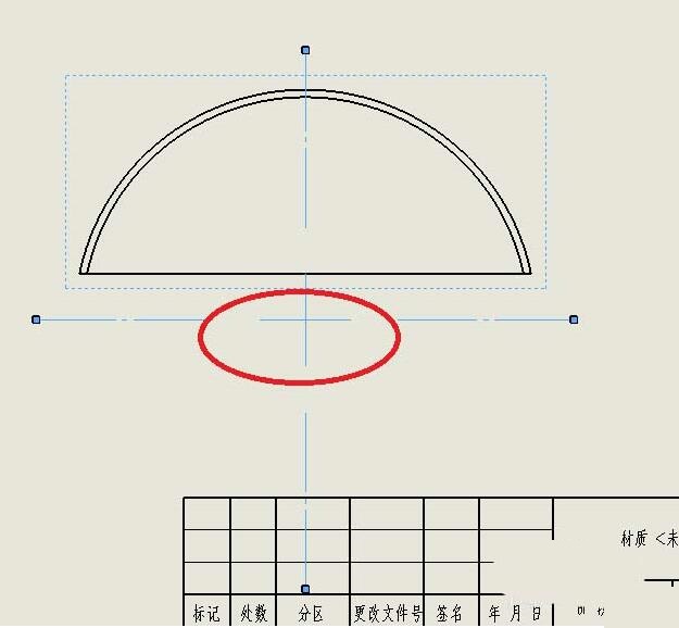
6、上一步刚刚选择完圆弧,这一步就如图所示,立马出现了中心符号线。
7、如图所示,点击“中心符号线”对话框左上角的√,完成中心符号线的添加操作。
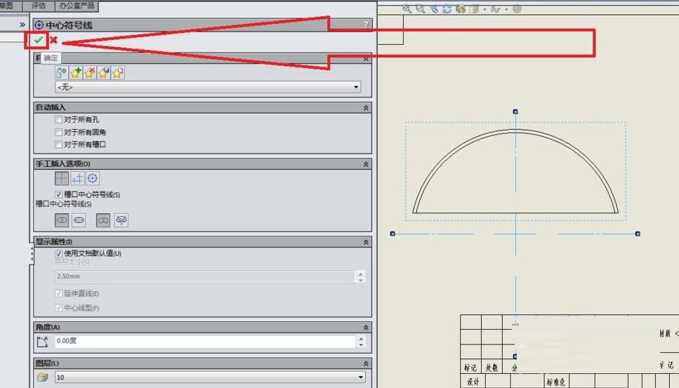
8、如图,成功的给我们刚刚选择的圆弧添加了一个中心符号线。
快来学习学习Solidworks工程图插入中心符号线的详细步骤吧,一定会帮到大家的。